
DirectX
In this article I will give a quick introduction to DirectX. I will use Visual Studio 2008 as a development environment for this tutorial and I will start by showing how to install DirectX and configure Visual Studio 2008 to start developing DirectX applications. I assume that the reader has basic programming knowledge in C++. If you require a math refresher, you can refer to my “3D Math Primer” articles on Coordinate Spaces, Vector Operations, and Matrices.
Introduction
DirectX is the name of the collection of application programming interfaces (APIs) provided by Microsoft for use on Microsoft’s Windows operating systems. DirectX was originally created to provide programmers a platform to continue developing games for the upcoming platform called Windows 95. Windows 95 offered a protected memory model that restricted users from having direct access to the peripherals of the computer such as the display device, the keyboard and mouse, and audio device. To overcome this restriction developers at Microsoft had to provide a set of programming APIs that allowed the developer to access these devices in a standardized way.
The DirectX software development kit (SDK) provides several APIs that perform specific functions. Direct3D is the most commonly used API and includes methods to render 3D graphics directly to the hardware accelerated render device. The DirectDraw API provides hardware accelerated 2D graphics drawing however this API has recently been deprecated in favor of Direct2D available on Windows 7. The DirectSound API is used for playing sound effects while DirectMusic (now deprecated) was used for the playback of music tracks and audio streams. More recently, Microsoft also introduced the XACT and XAudio2 API which is a layer built on the DirectSound API. The API that is responsible for providing access to input devices such as keyboards, mice, and joysticks is called DirectInput and an API was also introduced to provide network play functionality called DirectPlay but this API is also now deprecated in favor of Windows Sockets.
In this article, I will focus on the Direct3D API.
Installing DirectX
The DirectX SDK can be downloaded from Microsoft’s MSDN website at http://msdn.microsoft.com/en-us/directx/default. Every few months, Microsoft will release a new version of the SDK (the current version at the time of this writing is the June 2010 SDK) so if you are in early development of your project, you may want to check back to make sure you are using the most up-to-date version of the SDK.
Click the “Get the Latest DirectX SDK” as shown highlighted in the image below.
Once you have the SDK installer downloaded, you can run the installer by double-clicking on the file.
Setting up Visual Studio
If you already have Visual Studio installed, the DirectX installer will add a few settings to the general settings of Visual Studio. If you installed the DirectX SDK before you installed Visual Studio, you may have to add these settings yourself. Let us confirm that these settings are applied to your Visual Studio environment.
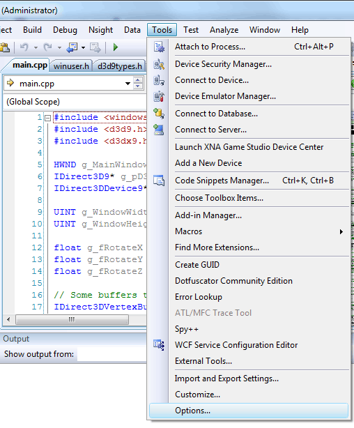
Open Visual Studio 2008 and select “Tools → Options…” from the main menu.
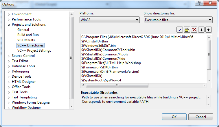
From the “Options” dialog that appears, select the “Projects and Solutions/VC++ Directories” list item.
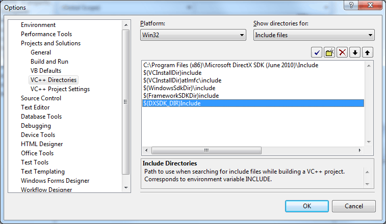
In the “Show directories for:” drop-down menu, select “Include files” option.
Confirm that the entry
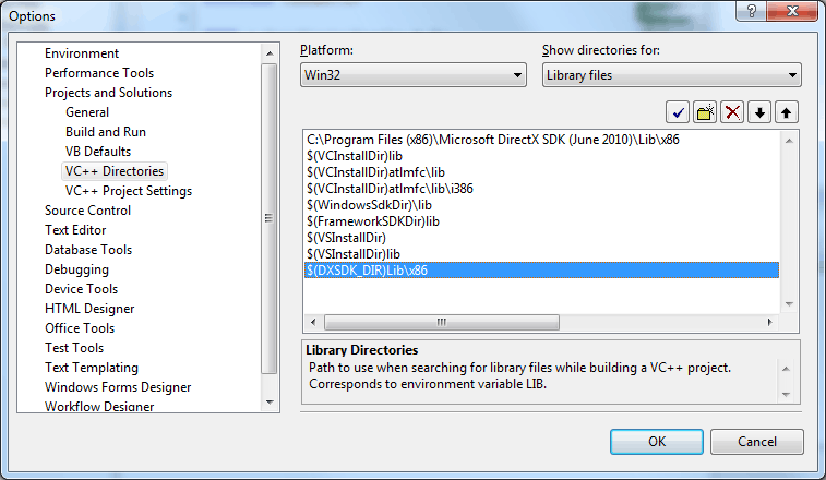
Now select the “Library files” option from the “Show directories for:” drop-down menu.
Confirm that the entry
Once you have confirmed these settings, you can start developing your DirectX applications.
Create a New Project
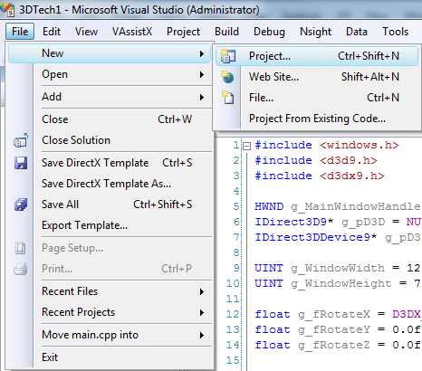
We first need to create a new project for the DirectX demo. From the main menu, select “File → New → Project…” or use the shortcut key Ctrl+Shift+N.
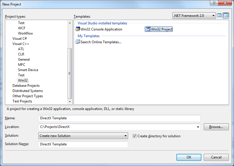
In the “New Project” dialog that appears, select “Visual C++/Win32” from the “Project types:” list, and in the “Templates:” pane, select the “Win32 Project” template.
Select a name for your new project (I choose “DirectX Template” for mine) and a location where your new project will be created. Click “OK” to create the new project.
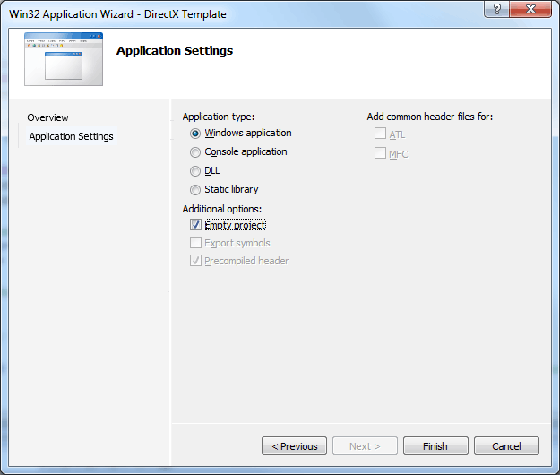
In the “Win32 Application Wizard” dialog box that appears, select the “Application Settings” item on the left and in the pane on the right, select “Windows application” radio button under “Application type:” and check the “Empty project” check box under “Additional options:”. Doing this will ensure we start with a clean project. In the following steps we will add the source files ourselves.
Click the “Finish” button to close the application wizard and create the new project in our solution.
Project Properties
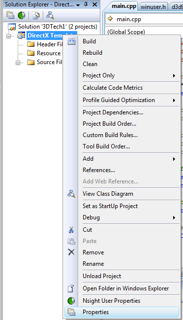
Before we can build our DirectX application, we must tell Visual Studio which libraries to link against. Right-click on the project node in the solution explorer and select “Properties” from the popup menu that appears.
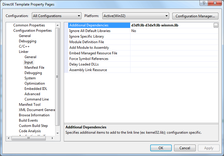
From the properties dialog that appears, select “All Configurations” from the “Configuration:” drop-down menu. This will ensure any changes we make will be applied to both the debug and release build target configurations. Then select “Configuration Properties/Linker/Input” from the list view and in the “Additional Dependencies” text field, add
Now with the project configure correctly, we can start programming our source code.
Programming the Source
For this demo, we will only have a single source file
Adding the Source File
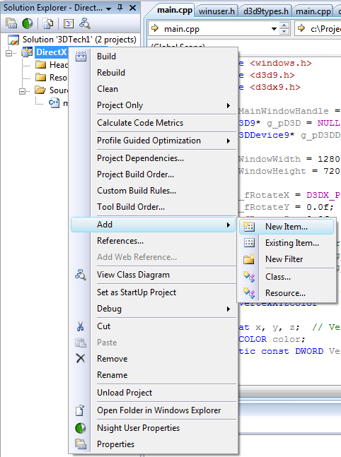
We will start by adding a new source file to the project. To do this, we will right-click on the project node in the solution explorer and select “Add → New Item…” from the popup menu that appears.
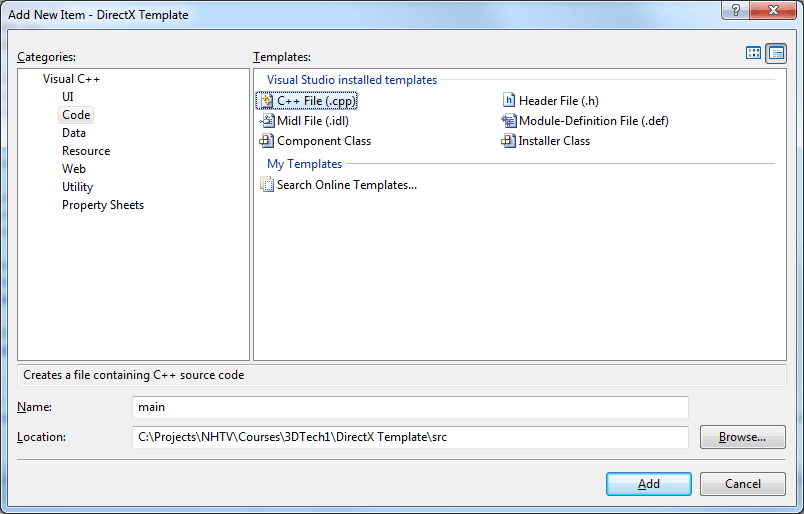
From the “Add New Item” dialog box that appears, select “Visual C++/Code” from the “Categories:” list and in the “Templates:” pane, select “C++ File (.cpp)”.
In the “Name:” field enter “main”, and I like to keep my cpp source files in a directory called “src” relative to the project folder as shown in the image above.
Headers and Global Variables
Open the newly created source file
|
1 2 3 |
#include <windows.h> #include <d3d9.h> #include <d3dx9.h> |
We only need 3 headers for this demo. The windows.h header file has everything we need to create basic windows applications. The core Direct3D API is contained in the d3d.h header file while the d3dx9.h header file contains some useful structures and methods that can ease the programming tasks that are required to create a DirectX application.
You could argue that we don’t need to include the d3d9.h header file if we are including the d3dx9.h header because the d3d9.h header will be included automatically in that header file.
|
45 46 |
// Includes #include "d3d9.h" |
We will also declare a few global variables that will be retained during the lifetime of the application.
|
5 6 7 8 9 10 11 12 13 14 |
HWND g_MainWindowHandle = 0; IDirect3D9* g_pD3D = NULL; IDirect3DDevice9* g_pD3DDevice = NULL; UINT g_WindowWidth = 1280; UINT g_WindowHeight = 720; float g_fRotateX = D3DX_PI / 4.0f; float g_fRotateY = 0.0f; float g_fRotateZ = 0.0f; |
The first thing we declare is a variable that will hold the handle to our applications main window. This is the window that will be used to render our amazing hardware-accelerated 3D graphics.
We also declare a variable to hold a reference to our Direct3D9 interface object. This variable is of type IDirect3D9 which is actually a COM object (Component Object Model). Window’s COM objects will not be discussed in detail in this tutorial but basically you should know you don’t create COM objects with the new operator and you don’t delete them with the delete operator. The only way you can free a COM object is by invoking the Release() method on that object (as we will see in the Cleanup() method). The Direct3D9 interface object is used to query the capabilities of the different graphics adapters in your computer if you have more than one. The other responsibility of the Direct3D9 interface object is to create the reference to the actual Direct3D device that will be used to render graphics to your screen.
The next parameter we declare is a pointer to another COM object and that is of type IDirect3DDevice9. This object refers to the actual Direct3D device that is responsible for drawing things to the screen.
We will also store the window’s current width and height variables in g_WindowWidth and g_WindowHeight respectively. These variables will be used to initialize the size of our window and the size of the back buffer surfaces that will be used by DirectX to draw to.
We also want to animate our objects with some rotation, so we will declare some parameters to store the current rotation of the object along each axis.
For efficient rendering of 3D objects DirectX provides buffer objects that can be used allocate memory directly on the graphics hardware. This way, when we want to draw the geometry, we simply tell DirectX that we want to render a specific set of vertices that are stored in a particular hardware buffer and the hardware will perform the transformation and lighting calculations directly on the hardware buffers. For this, we will use the IDirect3DVertexBuffer9 COM object. Also, if we don’t want to store redundant vertices to our geometry, we can create a vertex buffer that only contains unique vertices and then we use an index buffer to tell the DirectX rendering pipeline the order in which the vertices should be sent to the rendering pipeline to generate all the primitives for our model. To store the indices of our mesh, we will use an IDirect3DIndexBuffer9 COM object.
Lets now declare variables that will used to store a pointer to our object’s vertex buffer and index buffer.
|
16 17 18 |
// Some buffers to render a cube IDirect3DVertexBuffer9* g_CubeVertexBuffer = NULL; IDirect3DIndexBuffer9* g_CubeIndexBuffer = NULL; |
In order to populate our vertex buffer, we will need to define the type of data that it will store.
|
20 21 22 23 24 25 26 |
// Vertex definition for our vertex data struct VertexXYZColor { float x, y, z; // Vertex position. D3DCOLOR color; static const DWORD VertexFormat = D3DFVF_XYZ|D3DFVF_DIFFUSE; // Flexible vertex format definition for this vertex type }; |
The name of our vertex data structure is important to describe the type of data that it will contain. When your project gets bigger, you may need to define different vertex data types with different member variables. If you give your vertex data structure meaningful names, you will increase the chance that the data structure will be reused and reduce the chance that multiple vertex data structures that contain the same member variables will be declared. In this case we create a vertex data structure called VertexXYZColor so that we know it contains 3 components to store the X, Y, and Z position followed by a Color component. Another meaningful name for this structure could have been VertexPosColor, but then we wouldn’t know if it is a 4-component position (with X, Y, Z, and W) or a 3-component position vertex type.
The static member variable called VertexFormat is used describe the data that this vertex structure contains. This particular vertex type only contains the X, Y, Z for position followed by the diffuse color data that will be applied to the vertex. These parameters combined describes the “Flexible Vertex Format” (FVF) that is used to tell DirectX exactly what type of vertex we are providing to the rendering pipeline. It is worth noting that the order of the FVF bitfield is not really important, but what is very important is the order in which the member variables are declared in the vertex struct. If you are unsure what order these member variables must appear in, just take a look at the d3d9types.h header file and observe the order of the flexible vertex format bits in that file. In general, the members of the vertex will be declared in the following order:
D3DFVF_XYZ: Untransformed vertex position stored as 3 32-bit floating point values.D3DFVF_NORMAL: Untransformed vertex normal stored as 3 32-bit floating point values. For this demo, we won’t use lighting so we don’t need vertex normals.D3DFVF_PSIZE: Vertex point size stored as a single 32-bit floating point value. This component is generally only used for particle effects and it defines the size of a texture mapped screen-aligned particle in camera space. Since this vertex declaration is not for a particle effect, we won’t use this.D3DFVF_DIFFUSE: The diffuse color of the vertex stored as aD3DCOLORvalue. TheD3DCOLORvalue is just a 4-byte type that can store ARGB colors whose components can store a color value in the range 0-255.D3DFVF_SPECULAR: The specular color of the vertex stored as aD3DCOLORvalue. This is similar to the diffuse color just described.D3DFVF_TEX0 - D3DFVF_TEX8: Specify the number of texture coordinate sets that will appear in your vertex definition. This define does not actually describe a component, but it informs DirectX how many texture coordinate sets will be present in this vertex definition.D3DFVF_TEXCOORDSIZEN(CoordIndex): Texture coordinate sets for the vertex. TheNshould be replaced by 1, 2, 3, or 4 and describes the dimension of the texture coordinate as either 1, 2, 3, or 4-component texture coordinate. Each component of the texture coordinate is stored as a 32-bit floating point value. TheCoordIndexrefers to the texture index and can be an integer value between 0 and 7. For more information on texture coordinate formats, refer to the MSDN document Texture Coordinate Formats
An example from the MSDN documentation of a more complex vertex structure is shown below.
|
1 2 3 4 5 6 7 8 9 10 11 12 13 14 |
// This vertex format contains two sets of texture coordinates. // The first set (index 0) has 2 elements, and the second set // has 1 element. The description for this vertex format would be: // dwFVF = D3DFVF_XYZ | D3DFVF_NORMAL | D3DFVF_DIFFUSE | D3DFVF_TEX2 | // D3DFVF_TEXCOORDSIZE2(0) | D3DFVF_TEXCOORDSIZE1(1); // typedef struct CVF { D3DVECTOR position; D3DVECTOR normal; D3DCOLOR diffuse; float u, v; // 1st set, 2D float t; // 2nd set, 1D } CustomVertexFormat; |
As you can see, this vertex type defines a position, a normal, a diffuse color, and two sets of texture coordinates (D3DFVF_TEX2). The first texture coordinate set (at index 0) is for a 2D texture (D3DFVF_TEXCOORDSIZE2), while the second set (at index 1) is for a 1D texture (D3DFVF_TEXCOORDSIZE1).
We will also declare some helpful constants that describe a few common colors that we will use for our vertex data.
|
28 29 30 31 32 33 34 35 |
const D3DXCOLOR WHITE ( D3DCOLOR_XRGB( 255, 255, 255 ) ); const D3DXCOLOR BLACK ( D3DCOLOR_XRGB( 0, 0, 0 ) ); const D3DXCOLOR RED ( D3DCOLOR_XRGB( 255, 0, 0 ) ); const D3DXCOLOR GREEN ( D3DCOLOR_XRGB( 0, 255, 0 ) ); const D3DXCOLOR BLUE ( D3DCOLOR_XRGB( 0, 0, 255 ) ); const D3DXCOLOR YELLOW ( D3DCOLOR_XRGB( 255, 255, 0 ) ); const D3DXCOLOR CYAN ( D3DCOLOR_XRGB( 0, 255, 255 ) ); const D3DXCOLOR MAGENTA ( D3DCOLOR_XRGB( 255, 0, 255 ) ); |
The D3DCOLOR_XRGB is a useful macro that will let us specify the 32-bit color value as a set of red, green, and blue color components in the range 0 – 255. The alpha component is implicitly set to 255 (fully opaque). If you want to specify the alpha value yourself, you can use the D3DCOLOR_ARGB macro. If you want to specify the color components as floating point values, you can use the D3DCOLOR_COLORVALUE macro but the values must be in the range \([0.0 \cdots 1.0]\) (the macro will not clamp these values for you).
We will define our vertex data for a cube object using our custom vertex definition.
|
37 38 39 40 41 42 43 44 45 46 47 |
// Vertices of a unit cube VertexXYZColor g_CubeVertexData[8] = { { -1.0f, -1.0f, -1.0f, (D3DCOLOR)BLACK }, { -1.0f, 1.0f, -1.0f, (D3DCOLOR)GREEN }, { 1.0f, 1.0f, -1.0f, (D3DCOLOR)YELLOW }, { 1.0f, -1.0f, -1.0f, (D3DCOLOR)RED }, { -1.0f, -1.0f, 1.0f, (D3DCOLOR)BLUE }, { -1.0f, 1.0f, 1.0f, (D3DCOLOR)CYAN }, { 1.0f, 1.0f, 1.0f, (D3DCOLOR)WHITE }, { 1.0f, -1.0f, 1.0f, (D3DCOLOR)MAGENTA }, }; |
Our cube has 8 unique vertices and we will use a different color for each vertex. Each vertex is colored according to it’s position which results in a nice color cube that looks really pretty 🌈.
We also need to define the index buffer data.
|
49 50 51 52 53 54 55 56 57 58 59 60 61 62 63 |
WORD g_CubeIndexData[36] = { 0, 1, 2, 0, 2, 3, 4, 6, 5, 4, 7, 6, 4, 5, 1, 4, 1, 0, 3, 2, 6, 3, 6, 7, 1, 5, 6, 1, 6, 2, 4, 0, 3, 4, 3, 7, }; |
The values of the index buffer represent the index of the vertex in the vertex buffer that is used to render the geometry. Each 3-tuple represents a single triangle in the mesh. For our cube, there are 6 faces (quads) and each face requires 2 triangles and each triangle needs 3 vertices to be rendered for a total of 36 indices.
Forward Declarations
We will forward-declare the functions that will be used in our program.
|
65 66 67 68 |
// Initialize the windows application. bool InitWindowsApp( HINSTANCE instanceHandle, int show ); // Initialize DirectX bool InitDirectX( HINSTANCE hInstance, int width, int height, bool bWindowed, D3DDEVTYPE deviceType, IDirect3DDevice9** device ); |
These first two methods will be used to initialize the render window and the DirectX device respectively. Each method returns a Boolean value that indicates whether the method successful or not.
The next set of methods will control the life cycle of our application.
|
70 71 72 73 74 75 76 77 78 79 |
// Setup the application resources bool Setup(); // Handler for the windows message loop. int Run(); // Update our game logic void Update( float deltaTime ); // Render our scene void Render(); // Release resources void Cleanup(); |
The Setup() method will be used to setup our vertex buffer and index buffer that will be used to render the cube. This method will also setup the camera matrix and the projection matrix that are used to determine how we will view the scene. For this demo, these values only need to be set once so this method is a perfect place to do that.
The Run() method will start our game loop and consume and dispatch messages until a “quit” message is received. I will discuss the message loop in more detail later.
The Update() method is responsible for updating the game logic.
The Render() method will be used to render the game scene.
And when everything is finished and we close the application, the Cleanup() method is used to release references to our COM objects and cleanup allocated dynamic memory.
|
81 82 83 |
// The windows procedure. This method is used to handle events // that our window receives. LRESULT CALLBACK WndProc( HWND hWnd, UINT msg, WPARAM wParam, LPARAM lParam ); |
This is a declaration for the famous message processor that is associated to a particular window class. I will explain this method in more detail when we look at the definition.
The Main Entry Point
The WinMain() method is the main entry point for our application. This is where it all begins. This method is the beginning and the end of our application.
|
86 87 88 89 90 91 92 93 94 95 96 97 98 99 100 101 102 103 104 105 106 107 108 109 110 111 |
// The main entry point for windows applications. int WINAPI WinMain( HINSTANCE hInstance, HINSTANCE hPrevInstance, PSTR lpCmdLine, int nShowCmd ) { // Create and initialize the windows application. if ( !InitWindowsApp( hInstance, nShowCmd ) ) { MessageBox(0, TEXT("Application Initialization Failed"), TEXT("ERROR"), MB_OK ); return 0; } if ( !InitDirectX( hInstance, g_WindowWidth, g_WindowHeight, true, D3DDEVTYPE_HAL, &g_pD3DDevice ) ) { MessageBox( 0, TEXT("Failed to initilize DirectX"), TEXT("ERROR"), MB_OK ); } if ( !Setup() ) { MessageBox( 0, TEXT("Failed to setup application resources"), TEXT("ERROR"), MB_OK ); } int retCode = Run(); Cleanup(); return retCode; } |
The WinMain method takes several arguments.
HINSTANCE hInstance: This is the handle to the current application instance. It is used to uniquely identify the particular instance of your running program to the Windows operating system. You may have several instances of your application running in which case each instance will also get a unique handle.HINSTANCE hPrevInstance: The handle to the previous instance of the application. This parameter is not used in 32-bit Win32 applications and will always beNULL.LPSTR lpCmdLine: This is the command line that was passed to the program when it is executed excluding the executable file path. If you need to get the entire command line, use theGetCommandLine()method.int nCmdShow: Controls how the window is to be shown. For more information on thenCmdShowparameter, refer to the WinMain Entry Point documentation.
The first thing we do when we start our Windows application is create a window that will be used to render our graphics onto. This is done in the InitWindowApp() method on line 90. If something goes wrong with our window creation method, this function will return false and a message box will be displayed to the user.
If our window creation was successful we will then initialize the DirectX device using the InitDirectX() method on line 96. Again, if something should fail we will notify the user using a message box.
Now that we have a window to render onto and a DirectX device to render with, we’ll invoke the Setup() method on line 101 to initialize the graphics resources that our program uses. This method will also be used to setup the initial camera view and projection matrix.
The Run() method on line 106 will start our main message loop. This function will not return until the user quits the application at which time the error code will be returned.
Before we close the application, we also want to make sure that our DirectX resources are properly released so that the allocated buffer memory is returned back to the system heap for use by other applications. For this we use the Cleanup() method.
And finally, we’ll return the error code (0 if no error occurred) to the runtime and the application will be terminated.
The InitWindowsApp Method
The InitWindowsApp() method is responsible for registering and creating our application’s main window.
|
113 114 115 116 117 118 119 120 121 122 123 124 125 126 127 128 129 130 131 132 133 134 135 136 137 138 139 140 141 142 143 144 145 146 147 148 149 150 151 152 153 154 155 156 157 158 159 160 161 162 163 164 |
bool InitWindowsApp( HINSTANCE hInstance, int show ) { // Create a window description WNDCLASSEX wc; wc.cbSize = sizeof(WNDCLASSEX); wc.style = CS_HREDRAW | CS_VREDRAW | CS_OWNDC; wc.lpfnWndProc = WndProc; // Register the callback function for the window procedure wc.cbClsExtra = 0; wc.cbWndExtra = 0; wc.hInstance = hInstance; wc.hIcon = LoadIcon(hInstance, MAKEINTRESOURCE(IDI_MAIN_ICON)); wc.hCursor = LoadCursor( 0, IDC_ARROW ); wc.hbrBackground= static_cast<HBRUSH>( GetStockObject(WHITE_BRUSH) ); wc.lpszMenuName = NULL; wc.lpszClassName= TEXT("DirectX_Template"); wc.hIconSm = NULL; if ( !RegisterClassEx(&wc) ) { MessageBox( 0, TEXT("Failed to register window class."), NULL, 0 ); return false; } // Create a new window using the class description we just registered. g_MainWindowHandle = CreateWindowEx( WS_EX_OVERLAPPEDWINDOW, // DWORD dwExStyle TEXT("DirectX_Template"), // LPCWSTR lpClassName TEXT("DirectX Template"), // LPCWSTR lpWindowName WS_OVERLAPPEDWINDOW, // DWORD dwStyle CW_USEDEFAULT, // int X CW_USEDEFAULT, // int Y g_WindowWidth, // int nWidth g_WindowHeight, // int nHeight NULL, // HWND hWndParent NULL, // HMENU hMenu hInstance, // HINSTANCE hInstance NULL // LPVOID lpParam ); if ( g_MainWindowHandle == 0 ) { MessageBox( 0, TEXT("Failed to create main window"), NULL, 0 ); return false; } // And show and update the window we just created ShowWindow( g_MainWindowHandle, show ); UpdateWindow( g_MainWindowHandle ); return true; } |
This method takes two parameters:
HINSTANCE hInstance: This parameter is just passed from theWinMain()method and it is the handle to the instance of our running application. This parameter is necessary to define our window class description.int show: This is also just a passed-through parameter from theWinMain()method and determines how the window will be presented the first time.
Before we can create a new window for our application, we first have to describe the window we want to create. Since it is possible that our application can have multiple windows each with a different description, we need to create a window class and register it with the Windows system. We do this with the WINDCLASSEX structure definition. This structure has several members that are used to describe the window class.
UINT cbSize: Specifies the size of theWINDCLASSEXstructure in bytes and should be set tosizeof(WNDCLASSEX).UINT style: The class style defines additional functionality of the window. There are more window styles but I will only describe the ones used here.CS_HREDRAW: This will cause the entire window to be redrawn if the width of the window changes.CS_VREDRAW: This will cause the entire window to be redrawn if the height of the window changes.CS_OWNDC: This specifies that each window that is created from this class will have a unique device context associated with it.
WNDPROC lpfnWndProc: This is a pointer to the window procedure function that we forward-declared above. I will show the definition of this function later in the article.int cbClsExtra: Specifies the number of extra bytes to allocate following the window class structure. We won’t use this so we simply set it to0.int cbWndExtra: Specifies the number of extra bytes to allocate following the window instance. Again, we don’t use this so we simply set it to0.HINSTANCE hInstance: This is the handle to the application instance that was passed to this function.HICON hIcon: This member specifies the icon that is to be used to represent the window. TheLoadIcon()method is used to load an icon file from the executable’s resource database. I have an icon for this application that I got from the DirectX sample application which I calledIDI_MAIN_ICON. But if you don’t have an icon you can use the default application icon by specifyingIDI_APPLICATION.HCURSOR hCursor: This is a handle to the cursor that will be used when the mouse moves over the window. For this, we will just specify the default arrow cursor by usingIDC_ARROW.HBRUSH hdrBackground: A brush that will be used to paint the background of the window. Since we will be redrawing the full window every time we render the scene, the value we specify here won’t make much impact. We will just specify a default white brush usingWHITE_BRUSH.LPCSTR lpszMenuName: If your window has a menu, this member stores the null-terminated string name of the menu class as it appears in the resource file. Since we don’t have a menu for our window, we will just specifyNULL.LPCSTR lpszClassName: This is the name of the window class we are defining. This name will be used to identify the window class when we actually create an instance of the window usingCreateWindowEx.HICON hIconSm: A handle to the small icon that is used to represent the window. If this parameter isNULLthe icon that is specified in thehIconmember will be searched for an image that is an appropriate size to be used as the small icon.
Now that we have the definition of our window class, we use the RegisterClassEx() method to register our window class with the windows system. If there is something wrong with our window class definition, this method will fail in which case we will display a message box to the user notifying them of the problem.
To create an actual instance of the window class we just registered, we’ll use the CreateWindowEx() method and assign the result to our g_MainWindowHandle global parameter.
The CreateWindowEx() method accepts the following parameters:
DWORD dwExStyle: This parameter specifies the extended window parameter of the window being created. For our window we will specifyWS_EX_OVERLAPPEDWINDOWwhich is equivalent to the combination ofWS_EX_CLIENTEDGEandWS_EX_WINDOWEDGE. This creates a window with a border of both a sunken and raised window edge.LPCSTR lpClassName: This is the name of the window class definition that we specified when we registered our window class with the call toRegisterClassEx().LPCTSTR lpWindowName: This is the name of the window that will appear in the window’s title bar.DWORD dwStyle: Specifies the (non-extended) style of the window being created. In this case, we specifyWS_OVERLAPPEDWINDOWwhich is equivalent to combining theWS_OVERLAPPED,WS_CAPTION,WS_SYSMENU,WS_THICKFRAME,WS_MINIMIZEBOX, andWS_MAXIMIZEBOXstyles. This is the same as theWS_TILEDWINDOWwindow style.int x: The initial x-coordinate of the window’s upper-left corner in screen coordinates. TheCW_USEDEFAULTindicates that we want the system to choose a nice position for our window and theyparameter will have another meaning.int y: The initial y-coordinate of the window’s upper-left corner in screen coordinates. If an overlapped window is created with theWS_VISIBLEbit set and thexparameter is set toCW_USEDEFAULTand theyparameter is also set toCW_USEDEFAULT, then the window manager callsShowWindow()with theSW_SHOWflag after the window has been created. We will ignore this detail and callShowWindowexplicitly ourselves after our window is created.int nWidth, int nHeight: These parameters specify the width and height in screen coordinates of the window.HWND hWndParent: Specifies a handle to the parent window. Since we are creating a top-level window, this parameter will beNULL.HMENU hMenu: A handle to a menu to be used for the window. This value can be used to override the menu specified in the window class when the class was registered withRegisterClassEx. Since our window doesn’t use a menu, this value is stillNULL.HINSTANCE hInstance: A handle to the instance of the module to be associated with the window. This is the instance handle that refers to our running application.LPVOID lpParam: When the window is created, it will be given aWM_CREATEmessage by theCreateWindowEx()method before it returns. This parameter will be used as thelParamparameter of the passed message. Since we won’t handle theWM_CREATEmethod, this parameter can just beNULL.
If the window is successfully created, it will return a valid handle to the newly created window. If it failed, NULL will be returned in which case we will display a message box to the user indicating the error.
To ensure the window is visible we will call the ShowWindow() method passing along the show parameter.
The UpdateWindow() method will cause a WM_PAINT message to be sent directly to the window, but only if the window’s update region is not empty. In our case the windows update region is empty which means this function does nothing.
The Run Method
The Run() method is where our main game loop will be handled. This is where we will query for new messages that are waiting on the message queue and update the main game logic when there are no new messages to receive.
|
166 167 168 169 170 171 172 173 174 175 176 177 178 179 180 181 182 183 184 185 186 187 188 189 190 191 192 193 194 195 196 197 198 199 200 201 202 203 204 205 |
// This method encapsulates the windows message loop. int Run() { MSG msg; ZeroMemory( &msg, sizeof(MSG) ); static float previousTime = (float)timeGetTime(); static const float targetFramerate = 30.0f; static const float maxTimeStep = 1.0f / targetFramerate; // The message loop will run until the WM_QUIT message is received. while ( true ) { if ( PeekMessage( &msg, 0, 0, 0, PM_REMOVE ) ) { if ( msg.message == WM_QUIT ) break; // Translate the message and dispatch it to the appropriate // window procedure. TranslateMessage(&msg); DispatchMessage(&msg); } else { float currentTime = (float)timeGetTime(); // Calculate the delta time (in seconds) float deltaTime = ( currentTime - previousTime ) / 1000.0f; previousTime = currentTime; // Cap the delta (useful for debugging) deltaTime = min( deltaTime, maxTimeStep ); // If there are no messages to handle on the message queue, // update render our game. Update( deltaTime ); } } return msg.wParam; } |
The first thing we do in the Run() method is declare a MSG variable and initialize it to 0. The MSG structure is used to store message information for the a thread’s message queue.
Since we want to know how much time has elapsed between frames, we will initialize our timer variables to the current time using the timeGetTime() timer function. This function will return the elapsed system time since Windows was started in milliseconds. This function will only be available if you included the winmm.lib library in your additional dependencies properties in your project’s settings.
On line 177 we start the main message loop that will continue to run until the WM_QUIT message is received.
The PeekMessage() function will check the message queue if there are any messages that need to be dispatched to our window. Unlike the GetMessage() method, PeekMessage() will return a value of 0 (false) if there are no messages on the queue. We can take advantage of this by updating our game logic whenever there are no message to be processed. The parameters we are passing to PeekMessage() basically indicate that we should process all messages for all windows that are associated with the current thread and remove them from the message queue after they have been processed by PeekMessage().
If we receive the WM_QUIT message, we will break out of the loop and return control back to the main method ultimately terminating our running application. Otherwise we will translate and dispatch the incoming message.
The TranslateMessage() function translates virtual-key messages into character messages. This function does not actually modify the message parameter as the name of the function would suggest.
The DispatchMessage() function will dispatch the message to the appropriate window and invoke the window’s message processor that was specified to the lpfnWndProc member when the window class was registered. In this case, the WndProc() function defined below will be invoked.
If there are no messages to process on the message queue, we will update our game logic by calling the Update() method passing the amount of time in seconds that has elapsed since the previous call the Update() method.
The WndProc Method
The WndProc() method is our window’s main message processor.
|
207 208 209 210 211 212 213 214 215 216 217 218 219 220 221 222 223 224 225 226 227 228 229 230 231 232 233 234 235 236 237 238 239 240 241 242 243 244 245 246 247 248 249 250 251 252 253 254 255 256 257 258 259 260 261 262 |
LRESULT CALLBACK WndProc( HWND windowHandle, UINT msg, WPARAM wParam, LPARAM lParam ) { switch ( msg ) { case WM_PAINT: { Render(); // Redraw the window ValidateRect( windowHandle, NULL ); return 0; } break; case WM_KEYDOWN: // A key was pressed on the keyboard { switch ( wParam ) { case VK_ESCAPE: { DestroyWindow( g_MainWindowHandle ); } break; case 'f': case 'F': { // Switch to flat shading if ( g_pD3DDevice != NULL ) g_pD3DDevice->SetRenderState( D3DRS_SHADEMODE, D3DSHADE_FLAT ); } break; case 'g': case 'G': { // Switch to Gouraud shading if ( g_pD3DDevice != NULL ) g_pD3DDevice->SetRenderState( D3DRS_SHADEMODE, D3DSHADE_GOURAUD ); } break; case 'p': case 'P': { // Switch to Phong shading if ( g_pD3DDevice != NULL ) g_pD3DDevice->SetRenderState( D3DRS_SHADEMODE, D3DSHADE_PHONG ); } break; } return 0; } break; case WM_DESTROY: { PostQuitMessage( 0 ); return 0; } break; } // Forward unhandled messages to the default window procedure return DefWindowProc( windowHandle, msg, wParam, lParam ); } |
Although there are many more messages that could possibly be sent, for this demo we will only respond to three messages: WM_PAINT, WM_KEYDOWN, and WM_DESTROY. All additional messages will just be forwarded to the default window procedure for processing.
The WM_PAINT message is sent whenever the screen needs to be redrawn. In this case, we’ll just invoke the Render() method. We must also call ValidateRect() to validate the client area. Failing to do this will cause the system to continually generate WM_PAINT messages until the current update region is validated. If this happens, the message queue will always have a WM_PAINT message and our Update() method will never get a chance to execute.
The WM_KEYDOWN message is received whenever the user presses a nonsystem key. A nonsystem key is any key that is pressed while the ALT key is not pressed. In this case, the wParam parameter specifies the virtual-key code of the key that was pressed.
If the user presses the Esc key, the main window will be destroyed and a WM_DESTROY message will be sent to the window to deactivate it.
If the user presses the F key, we will set the shade mode to D3DSHADE_FLAT. Pressing G will change our shade mode to D3DSHADE_GOURAUD. And pressing the P key will change our shade mode to D3DSHADE_PHONG. Without lighting enabled, the D3DSHADE_GOURAUD and D3DSHADE_PHONG shading modes are indistinguishable.
If the WM_DESTROY message is received, we will post a WM_QUIT message using the PostQuitMessage() passing the exit code as the only parameter. The WM_QUIT message will be handled in our main loop which will cause the loop to terminate thus ending the application.
Any messages that aren’t handled are passed on to the default windows procedure DefWindowProc().
The InitDirectX Method
The InitDirectX method is responsible of initializing the DirectX device.
|
264 265 266 267 268 269 270 271 272 273 274 275 276 277 278 279 280 281 282 283 284 285 286 287 288 289 290 291 292 293 294 295 296 297 298 299 300 301 302 303 304 305 306 307 308 309 310 311 312 313 314 |
bool InitDirectX( HINSTANCE hInstance, int width, int height, bool bWindowed, D3DDEVTYPE deviceType, IDirect3DDevice9** device ) { // Create a Direct3D interface object g_pD3D = Direct3DCreate9(D3D_SDK_VERSION); if ( g_pD3D == NULL ) { MessageBox( 0, TEXT("Failed to create Direct3D interface object."), TEXT("Error"), MB_OK ); return false; } // Check for hardware vertex processing D3DCAPS9 deviceCaps; g_pD3D->GetDeviceCaps( D3DADAPTER_DEFAULT, D3DDEVTYPE_HAL, &deviceCaps ); int vertexProcessing = 0; if ( ( deviceCaps.DevCaps & D3DDEVCAPS_HWTRANSFORMANDLIGHT ) != 0 ) { vertexProcessing = D3DCREATE_HARDWARE_VERTEXPROCESSING; } else { // Hardware vertex processing not supported, fallback to software vertex processing. vertexProcessing = D3DCREATE_SOFTWARE_VERTEXPROCESSING; } D3DPRESENT_PARAMETERS d3dpp; ZeroMemory( &d3dpp, sizeof(D3DPRESENT_PARAMETERS) ); d3dpp.BackBufferWidth = width; d3dpp.BackBufferHeight = height; d3dpp.BackBufferFormat = D3DFMT_A8R8G8B8; // D3DFMT_UNKNOWN; d3dpp.BackBufferCount = 1; d3dpp.MultiSampleType = D3DMULTISAMPLE_NONE; d3dpp.MultiSampleQuality = 0; d3dpp.SwapEffect = D3DSWAPEFFECT_DISCARD; d3dpp.hDeviceWindow = g_MainWindowHandle; d3dpp.Windowed = bWindowed; d3dpp.EnableAutoDepthStencil = true; d3dpp.AutoDepthStencilFormat = D3DFMT_D24S8; d3dpp.Flags = 0; d3dpp.FullScreen_RefreshRateInHz = D3DPRESENT_RATE_DEFAULT; d3dpp.PresentationInterval = D3DPRESENT_INTERVAL_IMMEDIATE; if ( FAILED( g_pD3D->CreateDevice( D3DADAPTER_DEFAULT, deviceType, g_MainWindowHandle, vertexProcessing, &d3dpp, device ) ) ) { MessageBox( 0, TEXT("Failed to create Direct3D Device"), TEXT("Error"), MB_OK ); return false; } return true; } |
The first thing we have to do is get a reference to the Direct3D interface object. The global function Direct3DCreate9() is used to get that object. The only parameter we need to pass to this function is the D3D_SDK_VERSION constant. This is needed to ensure that the compiled version of Direct3D DLL matches with the version of the header files your programing is compiling against. If there is a version mis-match, this function will return NULL.
Using the Direct3D interface object we can query the capabilities of our graphics adapters that we have in our system. There is usually only one adapter which is specified by the D3DADAPTER_DEFAULT constant. We use the IDirect3D9::GetDeviceCaps() method to query the capabilities of the device so we can setup the device functionality with the best compatibility for our needs.
The only capability we are interested in is whether the default graphics adapter supports hardware vertex processing or only software vertex processing. Hardware vertex processing has a performance advantage over the software vertex processor so obviously we will want to use hardware vertex processing if it is available.
We do this by checking the D3DDEVCAPS_HWTRANSFORMANDLIGHT bit in the DevCaps member of the D3DCAPS9 structure. If the bit is set, we can use the hardware vertex transformation and lighting functionality of the rendering pipeline.
In order to create the Direct3D device, we need to specify the presentation parameters of the device. The members of the D3DPRESENT_PARAMETERS will determine how the device stores and presents the rendered images to the screen.
UINT BackBufferWidth, UINT BackBufferHeight: Specify the width and height of the back buffer surface in pixels.D3DFORMAT BackBufferFormat: The back buffer format specifies the bit-depth and layout of the back buffer surface. We useD3DFMT_A8R8G8B8to specify a 32-bit color surface with ARGB color components.UINT BackBufferCount: Specify the number of back buffers that will be created. This value can be between0andD3DPRESENT_BACK_BUFFERS_MAX.D3DMULTISAMPLE_TYPE MultiSampleType: The quality level of multisampling. Valid values range from 0 (D3DMULTISAMPLE_NONE) which means no multisampling will occur, up to 16 times multisampling (D3DMULTISAMPLE_16_SAMPLES).DWORD MultiSampleQuality: The quality of the multisampling algorithm. Since we aren’t using multisampling, we will simply specify0.D3DSWAPEFFECT SwapEffect: Indicates how the back buffer is to be handled when the screen needs to be presented.D3DSWAPEFFECT_DISCARDmeans that we can’t make any assumptions about the contents of the back buffer and should make sure that the entire contents of the screen are updated before invoking aPresent()operation. UsingD3DSWAPEFFECT_FLIPorD3DSWAPEFFECT_COPYguarantees that anDirect3DDevice9::Present()operation will not effect the contents of any of the back buffers, however this comes at a cost and we avoid using these swap effects unless we are aware of this overhead but our implementation requires it.HWND hDeviceWindow: This the handle to the window on which we want to render our scene onto. In this case, it is the main window handle that we created previously.BOOL Windowed: Whether or not the application should run in full-screen mode or not. A value ofTRUEmeans that it will render in a window, and a value ofFALSEmeans it will be rendered full-screen.BOOL EnableAutoDepthStencil: If this value isTRUE, Direct3D will manage depth buffers for the application. The device will create a depth-stencil buffer when it is created. The depth-stencil buffer will be automatically set as the render target of the device.D3DFORMAT AutoDepthStencilFormat: If theEnableAutoDepthStencilmember isTRUE, then this value must specify a valid format for the depth-stencil buffers. We will useD3DFMT_D24S8which indicates our depth-stencil buffer will be 32-bits wide with the first 24-bits per pixel containing the depth channel and the last 8-bits being used for the stencil channel. For more information about surface formats you can refer to theD3DFORMATdocumentation on MSDN.DWORD Flags: Additional present parameters can be specified using theFlagsmember. For a complete list of flags, please refer to theD3DPRESENTFLAG. For our demo, we don’t need to specify any additional flags. Some commonly used flags are:D3DPRESENTFLAG_LOCKABLE_BACKBUFFER: Specify that the back buffer can be locked. Keep in mind that locking the back buffer can cause a performance hit.D3DPRESENTFLAG_DISCARD_DEPTHSTENCIL: If this flag is set, the contents of the depth-stencil buffer will be invalid after callingIDirect3DDevice9::Presentbut may provide a performance increase.
UINT FullScreen_RefreshRateInHz: The rate at which the display adapter refreshes the screen. For windowed mode, the refresh rate must be 0.UINT PresentationInterval: The maximum rate at which the swap chain’s back buffers can be presented to the front buffer. For a detailed explanation of the modes and the intervals that are supported, seeD3DPRESENT.
Now that we have defined our presentation parameters, we are ready to create the Direct3DDevice object. We use the IDirect3D9::CreateDevice to create an interface to the the Direct3DDevice object. Passing as arguments, the display adapter ID for which to create the device for, the type of the device, a handle to our main window, a Boolean which indicates the vertex processing mode, the device presentation parameters, and the out parameter that is used to hold the reference to our newly created device. If this method returns D3D_OK then everything went okay and we should have a reference to a valid Direct3DDevice object.
The Setup Method
The Setup() method is used to initialize the buffers that will store the geometry information in the graphics memory.
|
316 317 318 319 320 321 322 323 324 325 326 327 328 329 330 331 332 333 334 335 336 337 338 339 340 341 342 343 344 345 346 347 348 349 350 351 352 353 354 355 356 357 358 359 |
bool Setup() { if ( g_pD3DDevice == NULL ) { MessageBox( 0, TEXT("NULL reference to D3DDevice"), TEXT("Error"), MB_OK ); return false; } // Create the vertex buffer and index buffer for our cube g_pD3DDevice->CreateVertexBuffer( 8 * sizeof(VertexXYZColor), D3DUSAGE_WRITEONLY, VertexXYZColor::VertexFormat, D3DPOOL_MANAGED, &g_CubeVertexBuffer, NULL ); g_pD3DDevice->CreateIndexBuffer( 36 * sizeof(WORD), D3DUSAGE_WRITEONLY, D3DFMT_INDEX16, D3DPOOL_MANAGED, &g_CubeIndexBuffer, NULL ); // Fill the buffers with the cube data VertexXYZColor* vertices = NULL; g_CubeVertexBuffer->Lock( 0, 0, (void**)&vertices, 0 ); memcpy_s(vertices, 8 * sizeof(VertexXYZColor), g_CubeVertexData, 8 * sizeof(VertexXYZColor) ); g_CubeVertexBuffer->Unlock(); // Fill the index buffer with the cube's index data WORD* indices = NULL; g_CubeIndexBuffer->Lock( 0, 0, (void**)&indices, 0 ); memcpy_s(indices, 36 * sizeof(WORD), g_CubeIndexData, 36 * sizeof(WORD) ); g_CubeIndexBuffer->Unlock(); // Setup the view matrix D3DXVECTOR3 cameraPosition( 0.0f, 0.0f, -5.0f ); D3DXVECTOR3 cameraTarget( 0.0f, 0.0f, 0.0f ); D3DXVECTOR3 cameraUp( 0.0f, 1.0f, 0.0f ); D3DXMATRIX viewMatrix; D3DXMatrixLookAtLH( &viewMatrix, &cameraPosition, &cameraTarget, &cameraUp ); g_pD3DDevice->SetTransform( D3DTS_VIEW, &viewMatrix ); // Setup the projection matrix D3DXMATRIX projectionMatrix; D3DXMatrixPerspectiveFovLH( &projectionMatrix, D3DX_PI / 4, (float)g_WindowWidth / (float)g_WindowHeight, 0.1f, 100.0f ); g_pD3DDevice->SetTransform( D3DTS_PROJECTION, &projectionMatrix ); // Disable lighting g_pD3DDevice->SetRenderState( D3DRS_LIGHTING, false ); return true; } |
After checking our preconditions, we can allocate the buffers that will be used to store our geometry data on the GPU memory for efficient rendering. We use the IDirect3DDevice9::CreateVertexBuffer() method to create the vertex buffer and the IDirect3DDevice9::CreateIndexBuffer() to create the index buffer.
The following parameters are shared by both the CreateVertexBuffer() and CreateIndexBuffer() methods:
UINT Length: The size of the buffer in bytes.DWORD Usage: Can be a combination of one or more of the usage flags specified inD3DUSAGE. Since we will only be writing to the buffers once, we will use theD3DUSAGE_WRITEONLYfor both the index buffer and index buffer. If we needed to make frequent updates to the buffers (in the case of particle systems for example, where the vertices positions will be modified every frame) we would also want to use theD3DUSAGE_DYNAMICusage flag.D3DFORMAT Format: A member of theD3DFORMATenumerated type which describes the format of the buffer.D3DPOOL Pool: A member of theD3DPOOLenumerated type.D3DPOOL_MANAGEDimplies the memory will be managed by Direct3D. Resources created in theD3DPOOL_MANAGEDmemory pool are backed by system memory and do not need to be recreated when the device is lost. Buffers created in the managed memory pool can be locked and modified by the host application and Direct3D will copy the memory to the device if the device memory becomes invalidated (by a modification to the system memory).IDirect3DIndexBuffer9 **ppIndexBuffer,IDirect3DIndexBuffer9 **ppIndexBuffer: Address of a pointer to the buffer interface which will be used to store the created buffer object.HANDLE *pSharedHandle: This is a reserved parameter. Just set it toNULL.
The parameter that is unique to the CreateVertexBuffer() method:
DWORD FVF: This is the flexible vertex format that was described above when we declared the custom vertex definition.
Before we can populate the buffers with our geometry data, we must acquire the buffer memory. We do this by locking the buffer for writing using the IDirect3DVertexBuffer9::Lock() and IDirect3DIndexBuffer9::Lock() method. We first lock the entire buffer, then copy the data from our local vertex buffer, or index buffer and unlock the buffer with the Unlock() method which will release control of the buffer memory back to the graphics device.
The second half of the Setup() method is used to initialize the camera and projection matrices. We use the helper functions provided by the d3dx9 library to simplify this operation.
The last thing we do (on line 356) is disable lighting render state using the IDirect3DDevice9::SetRenderState() method.
We are now ready to start rendering our scene!
The Cleanup Method
The Cleanup() method is used to release all the system resources that our program has allocated. This includes any COM objects that we may have references to, or any dynamic allocated memory used by our application.
|
361 362 363 364 365 366 367 368 369 370 371 372 373 374 375 376 377 378 379 380 381 382 383 384 385 386 387 388 389 |
void Cleanup() { // Release our resources if ( g_CubeVertexBuffer != NULL ) { g_CubeVertexBuffer->Release(); g_CubeVertexBuffer = NULL; } if ( g_CubeIndexBuffer != NULL ) { g_CubeIndexBuffer->Release(); g_CubeIndexBuffer = NULL; } // Release the Direct3D device if ( g_pD3DDevice != NULL ) { g_pD3DDevice->Release(); g_pD3DDevice = NULL; } // Release the Direct3D interface object if ( g_pD3D != NULL ) { g_pD3D->Release(); g_pD3D = NULL; } } |
This method is pretty straight forward, it simply releases the references to the COM object in the reverse order that they were allocated.
The Update Method
The Update() method is responsible for updating our main game logic.
|
391 392 393 394 395 396 397 398 399 400 401 402 403 404 405 406 |
void Update( float deltaTime ) { // Rate of rotation in units/second const float fRotationRateY = D3DX_PI / 4.0f; const float fRotationRateZ = D3DX_PI / 2.0f; g_fRotateY += fRotationRateY * deltaTime; g_fRotateZ += fRotationRateZ * deltaTime; // Clamp to the allowed range g_fRotateY = fmodf( g_fRotateY, D3DX_PI * 2.0f ); g_fRotateZ = fmodf( g_fRotateZ, D3DX_PI * 2.0f ); // Redraw our window RedrawWindow( g_MainWindowHandle, NULL, NULL, RDW_INTERNALPAINT ); } |
The only thing this demo application does is update our rotation parameters that are used to orientate our cube.
The RedrawWindow() will cause a WM_PAINT message to be queued to the window referenced by the g_MainWindowHandle variable. The last parameter RDW_INTERNALPAINT forces the entire client are to be invalidated and a WM_PAINT message to be posted on the message queue.
The Render Method
The Render() method is used to actually draw the content. Finally, the method you have all been waiting for! You might be a little disappointed when you see how short this method is 🙄.
|
408 409 410 411 412 413 414 415 416 417 418 419 420 421 422 423 424 425 426 427 428 429 430 431 432 433 434 435 |
void Render() { if ( g_pD3DDevice == NULL) { return; } // Setup our world matrix based on the rotation parameters D3DXMATRIX rotateX, rotateY, rotateZ; D3DXMatrixRotationX( &rotateX, g_fRotateX ); D3DXMatrixRotationY( &rotateY, g_fRotateY ); D3DXMatrixRotationZ( &rotateZ, g_fRotateZ ); D3DXMATRIX worldMatrix = rotateX * rotateY * rotateZ; g_pD3DDevice->SetTransform( D3DTS_WORLD, &worldMatrix ); // Render the scene g_pD3DDevice->Clear( 0, NULL, D3DCLEAR_TARGET|D3DCLEAR_ZBUFFER, D3DCOLOR_XRGB(55,55,55), 1.0f, 0 ); g_pD3DDevice->BeginScene(); g_pD3DDevice->SetStreamSource( 0, g_CubeVertexBuffer, 0, sizeof(VertexXYZColor) ); g_pD3DDevice->SetIndices( g_CubeIndexBuffer ); g_pD3DDevice->SetFVF( VertexXYZColor::VertexFormat ); g_pD3DDevice->DrawIndexedPrimitive(D3DPT_TRIANGLELIST, 0, 0, 8, 0, 12 ); g_pD3DDevice->EndScene(); g_pD3DDevice->Present( NULL, NULL, NULL, NULL ); } |
The first thing this method does after checking the preconditions, is setup the rotation matrix for our object. For this, we will use the rotation helper functions provided by the d3dx library to build our per-axis rotations. We can combine the rotations using matrix multiplication operator provided by the D3DXMATRIX class.
Then we set the world transform matrix that will be used to position and orient our object in the world using the IDirect3DDevice9::SetTransform() method.
We use the IDirect3DDevice9::Clear() to clear the contents of both the color buffer (D3DCLEAR_TARGET) and the depth (D3DCLEAR_ZBUFFER) buffers to dark-gray, and 1.0 respectively. The final parameter is the value to clear the stencil buffer, but since we aren’t using the stencil buffer, it doesn’t need to be cleared.
All rendering code must be wrapped between calls to IDirect3DDevice9::BeginScene() and IDirect3DDevice9::EndScene(). Multiple non-nested calls the these methods are allowed but doing this may incur a performance hit.
In order to render our geometry, we must perform the following four steps:
IDirect3DDevice9::SetStreamSource: This method is used to bind the vertex buffer to a data stream. The parameters to this function describe the data that is to be bound to the particular stream.UINT StreamNumber: Specifies the data stream to bind the vertex buffer to. This value can be in the range from 0 to maximum number of streams – 1.IDirect3DVertexBuffer9 *pStreamData: The vertex buffer to bind to the processor stream.UINT OffsetInBytes: The offset from the beginning of the stream to the beginning of the vertex data, in bytes.UINT Stride: The stride of a single vertex.
IDirect3DDevice9::SetFVF: Set the fixed function vertex format for our custom vertex type. This is just the flexible vertex format for our custom vertex declaration.IDirect3DDevice9::SetIndices: This is optional if we are using an index buffer. The only argument to this function is a pointer to the index buffer for our mesh.IDirect3DDevice9::DrawIndexedPrimitive: Renders the specified vertices to the rendering pipeline. The following parameters are used to specify how the vertices are to be rendered:D3DPRIMITIVETYPE Type: Describes the type of primitive to render.D3DPT_TRIANGLELISTwill render the vertices as a sequence of isolated triangles. Each set of three vertices (determined by the index buffer) defines a separate triangle.INT BaseVertexIndex: The offset in the vertex buffer to the first vertex to render. We want to render all the vertices in the vertex (and index) buffer so we will specify0for this parameter.UINT MinIndex: Minimum vertex index for vertices used during this call. This is a zero based index relative to BaseVertexIndex.UINT NumVertices: The number of vertices to render. The first vertex is located at index:BaseVertexIndex+MinIndex.UINT StartIndex: Index of the first index to use when accessing the vertex buffer.UINT PrimitiveCount: The number of primitives to render. Since our cube consists of 6 sides, each with 2 triangles, and we’re rendering triangles, we want to render 12 primitives.
And finally, to finalize and present the entire screen we use the IDirect3DDevice9::EndScene() and IDirect3DDevice9::Present() methods.
Conclusion
In this article, you learned how to setup a windows application, create and initialize a Direct3DDevice object and render a simple primitive to the screen. This is hardly an exhaustive tutorial on how to creating the next-gen, blockbuster 3D graphics engine but hopefully it is a good place to start learning how to make that next-gen, triple-A, blockbuster, 3D graphics rendering engine.
Please leave a comment to let me know if you were able to gain any knowledge from this article, or if you see any corrections that need to be made. Of if there is anything that you thing I should add to this article.
References
|
Frank D. Luna (2003). Introduction to 3D Game Programming with DirectX 9.0. Wordware Publishing, Inc. |
Download the Source
You can download the source code (including Visual Studio 2008 project files):


“int nWidth, int nHeight: These parameters specify the width and height in screen coordinates of the window.”
These are not actually defined.
Mark,
Although this is a very old (and outdated) article, you are the first one to point this out. (*I recommend you follow the new articles on DirectX 11 or 12 🙂
For clarity, you are referring to the parameters that are sent to the
CreateWindowExmethod on line 138. For some bizarre reason, sending theg_WindowWidthandg_WindowHeightto that method was omitted from the code snippet in this tutorial. I have resolved this now. Thank you for pointing it out!